English
 Arabic
 French
 Spanish
 Portuguese
 Deutsch
 Turkish
 Dutch
Dutch
 Italiano
 Russian
 Romaian
 Portuguese (Brazil)
 Greek
Greek
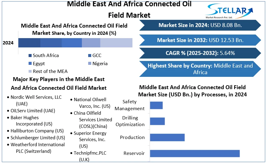
Middle East and Africa Connected Oil Field Market: Driving Digital Transformation in Energy Operations
Other |
2026-05-18 06:58:02
Achieving consistent quality in CNC internal cylindrical grinding requires a systematic approach that addresses process parameters, grinding wheel specification, coolant management, and dimensional verification in an integrated framework. Unlike external cylindrical grinding where the tooling geometry is relatively straightforward, internal grinding confronts the process engineer with a constellation of interacting variables — wheel speed limitations imposed by bore diameter, thermal effects amplified by the confined geometry, and vibration modes unique to the slender spindle extension — that demand careful optimization to achieve the roundness, cylindricity, and surface finish specifications that precision components require. The CNC internal grinding machine's primary specifications guide this optimization: bore range of 15-200 mm, roundness to 2 μm, cylindricity to 3-4 μm, and surface roughness to Ra 0.32 μm.
Depth of cut programming for CNC internal grinding follows a three-stage strategy that distinguishes roughing, semi-finishing, and finishing passes. The roughing phase uses infeed rates of 0.02 to 0.05 mm per stroke to efficiently remove the bulk of the grinding allowance, typically 0.2 to 0.5 mm total stock on a precision bore. Semi-finishing at 0.005 to 0.01 mm per stroke refines the bore geometry, bringing roundness error and cylindricity within range of the finishing specification. The finishing phase reduces infeed to 0.001 to 0.003 mm per stroke, taking the surface finish down to the Ra 0.32 μm target while the spark-out passes — where no additional infeed is programmed — allow residual cutting forces to decay and the bore to spring back to its free-state geometry. This three-stage approach, executable through parametric CNC programs that the operator customizes by inputting initial stock, target size, and tolerance, represents the standard best practice for precision internal grinding machine operation.
Wheel speed management addresses the fundamental constraint that makes internal grinding more complex than external grinding. For a wheel grinding a 50 mm diameter bore, the maximum usable wheel diameter is approximately 35-40 mm. At a modest spindle speed of 12,000 rpm, this 35 mm wheel achieves a surface cutting speed of only 22 m/s — below the 25-35 m/s range that delivers good cutting action with standard aluminum oxide wheels. The CNC machine's variable-speed motorized spindle compensates by allowing speed selection based on wheel diameter: smaller wheels require higher spindle speeds to maintain adequate cutting velocity. This is why the wheel speed on precision internal grinders is listed as "optional" in specifications — it requires selection based on the specific wheel diameter and workpiece material rather than a fixed machine parameter. Operators must calculate the appropriate RPM setting for each job setup, a step that many production facilities formalize in process sheets to ensure consistency across shifts.
Thermal management in internal grinding deserves particular attention because the confined bore geometry limits coolant access to the cutting zone. Inadequate cooling causes workpiece thermal expansion that temporarily shifts bore diameter away from the true cold-state dimension, creating parts that appear in-tolerance during grinding but grow out of tolerance as they cool. Effective coolant delivery requires nozzles positioned to direct high-velocity coolant flow directly into the gap between the grinding wheel and workpiece bore wall, with flow rates calculated to carry chips away before they can be re-cut. For difficult-to-machine materials such as hardened bearing steels (60-65 HRC), high-pressure coolant at 40-80 bar through-spindle delivery maintains the thermal stability needed to hold roundness within the 2 μm specification throughout a full production run. The workhead speed of 100-800 rpm creates centrifugal forces that assist coolant penetration into the grinding zone when optimized in conjunction with wheel speed for the specific bore diameter.
Dressing cycle management maintains grinding wheel sharpness throughout production runs. Diamond dressers positioned on the machine table perform wheel reconditioning in a CNC-controlled sequence between batches, restoring wheel roundness and cutting action. For CBN wheels, dressing frequency should be minimized — CBN wheels dressed too frequently lose their economic advantage. The 28 kW spindle power on the MK2120B ensures adequate torque to drive large CBN wheels even between dressing cycles.
In-process gauging integration transforms the CNC internal grinder from an open-loop system dependent on wheel wear compensation calculations into a closed-loop system that directly measures the workpiece and corrects for dimensional drift. Air gauging systems, where precisely machined nozzles are inserted into the bore between grinding passes and the back pressure measured against a calibration standard, can measure bore diameter to ±0.5 μm accuracy in under two seconds. When the gauging system feeds dimensional data back to the CNC controller, the machine can automatically calculate and apply the X-axis correction needed to bring the next piece to target size — compensation that would otherwise require periodic manual measurement and program adjustment by the operator. This automatic size control capability is essential for maintaining ±0.015 mm size dispersity across long production runs, particularly when temperature changes during day-shift versus night-shift operation would otherwise cause gradual dimensional drift.
Quality verification beyond grinding requires a comprehensive inspection protocol. CMM measurement with 0.1 μm resolution confirms the 2 μm roundness specification. Surface roughness profilometry at multiple axial positions detects cylindrical form errors. For bearing ring applications, Fourier analysis of roughness traces identifies periodic waviness that the Ra parameter alone cannot capture — providing the objective evidence that quality systems require to release precision components for assembly.
The evolution of CNC internal grinding machine technology continues as manufacturers integrate adaptive process control and IIoT connectivity. Adaptive control systems monitor spindle power and vibration in real time, detecting wheel loading and adjusting infeed rates before surface finish degrades. Digital twin models calibrated against actual machine behavior enable engineers to simulate new applications before committing to production setups. As precision manufacturing continues its quality trajectory, the CNC internal grinder remains indispensable for producing the exact bore geometries that modern mechanical systems require.